
Microsoft SQL Server
ERD (Data Model)
An Entity-Relationship Diagram (ERD) is a visual representation of the data model in a relational database. It illustrates the structure of the database, showing how different tables (entities) are related to each other. An ERD helps in designing the database by defining entities, their attributes, and the relationships between them. In Microsoft SQL Server, an ERD can be used to plan and organize tables before actual implementation.
Key Concepts of ERD:
Entities (Tables)
- Entities represent real-world objects or concepts, and each entity corresponds to a table in the database. For example,
Stores,Products, andCustomersare entities in a store database.
Example SQL (creating the
Storesentity):CREATE TABLE Stores ( StoreID INT PRIMARY KEY, StoreName VARCHAR(100), Location VARCHAR(100) );- Entities represent real-world objects or concepts, and each entity corresponds to a table in the database. For example,
Attributes (Columns)
- Attributes are the properties or fields that describe each entity. In a table, these are the columns. Each attribute has a data type, such as
INT,VARCHAR, orDATE.
Example SQL (attributes for the
Productsentity):CREATE TABLE Products ( ProductID INT PRIMARY KEY, ProductName VARCHAR(100), Price DECIMAL(10, 2), StoreID INT );- Attributes are the properties or fields that describe each entity. In a table, these are the columns. Each attribute has a data type, such as
Primary Key (Unique Identifier)
- Each entity must have a Primary Key to uniquely identify each record in the table. The primary key is often an
IDfield likeProductIDorCustomerID.
Example SQL (defining primary key in the
Customerstable):CREATE TABLE Customers ( CustomerID INT PRIMARY KEY, CustomerName VARCHAR(100), Email VARCHAR(100) );- Each entity must have a Primary Key to uniquely identify each record in the table. The primary key is often an
Relationships (Foreign Keys)
- Relationships define how entities (tables) are related to each other. This is usually done using Foreign Keys, which link the primary key of one table to a column in another table. There are three types of relationships:
- One-to-One: A row in one table corresponds to exactly one row in another table.
- One-to-Many: A row in one table corresponds to multiple rows in another table.
- Many-to-Many: Multiple rows in one table correspond to multiple rows in another table, typically handled by a junction table.
Example SQL (defining a one-to-many relationship between
StoresandProducts):CREATE TABLE Products ( ProductID INT PRIMARY KEY, ProductName VARCHAR(100), Price DECIMAL(10, 2), StoreID INT, FOREIGN KEY (StoreID) REFERENCES Stores(StoreID) );- Relationships define how entities (tables) are related to each other. This is usually done using Foreign Keys, which link the primary key of one table to a column in another table. There are three types of relationships:
Cardinality
- Cardinality specifies the number of relationships between entities. Common cardinalities include:
- One-to-One (1:1): Each row in Table A relates to only one row in Table B.
- One-to-Many (1:N): One row in Table A relates to multiple rows in Table B.
- Many-to-Many (M:N): Multiple rows in Table A relate to multiple rows in Table B, often requiring a join or junction table.
Example SQL (handling many-to-many relationship with a junction table):
CREATE TABLE CustomerOrders ( CustomerID INT, ProductID INT, OrderDate DATE, PRIMARY KEY (CustomerID, ProductID), FOREIGN KEY (CustomerID) REFERENCES Customers(CustomerID), FOREIGN KEY (ProductID) REFERENCES Products(ProductID) );- Cardinality specifies the number of relationships between entities. Common cardinalities include:
ERD Components
- Entities: Represented as rectangles (tables) in the ERD.
- Attributes: Represented as ovals (columns) connected to entities.
- Relationships: Represented by diamonds (foreign key relationships) between entities.
- Keys: The primary key is usually underlined in the diagram to signify its role in uniquely identifying records.
Benefits of ERD
- Clear Visualization: ERDs offer a clear, visual way to understand the relationships between different tables in a database.
- Better Database Design: They help in designing the database schema properly, ensuring efficient queries and data integrity.
- Simplifies Communication: ERDs are useful for explaining the database structure to non-technical stakeholders.
By designing and referencing an Entity-Relationship Diagram (ERD), you can create a well-structured and efficient database model that represents real-world relationships between your data. This ensures that your database is both organized and scalable for future needs.
Components of an ERD
Entities
These are objects or concepts that can have data stored about them. An entity represents a table in a database. Entities are usually nouns, such as Customer, Order, or Product.
Attributes
These are the data we store about an entity. They represent the columns in a table. For example, an Employee entity might have attributes such as Employee_ID, Name, and Department.
Relationships
These illustrate how entities share information in the database and are the lines that connect entities. Relationships show how two entities share information and interact with each other. They can be one-to-one, one-to-many, or many-to-many.
Primary Key (PK)
This is a unique attribute (or combination of attributes) that identifies a specific instance of an entity. Each entity in the ERD must have a primary key.
Foreign Key (FK)
This is an attribute in one entity that links to the primary key of another entity, establishing a relationship between the two entities.
Types of ERDs
Conceptual ERD
This is the most abstract form of ERD. It focuses on the high-level design and concept without including details like primary keys or attributes. It's used in the initial planning phase.
Logical ERD
This type adds more detail to the conceptual ERD by including key attributes for each entity and relationships. It does not include detailed attributes or methods but focuses on the structure of data.
Physical ERD
This is the most detailed ERD and includes all entities, relationships, key attributes, and constraints. It is directly used to implement the database schema in a specific database management system (DBMS).
CONCEPTUAL DATA MODEL
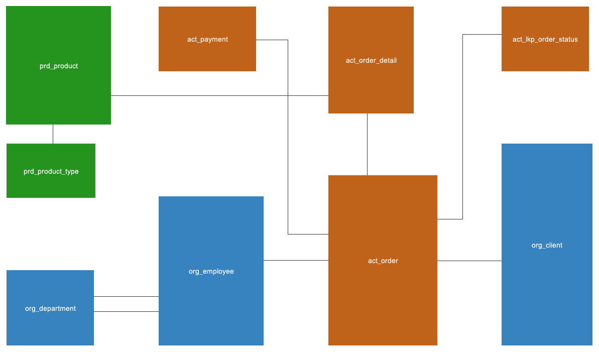
Only entities and their corresponding relationships are depicted here.
LOGICAL DATA MODEL
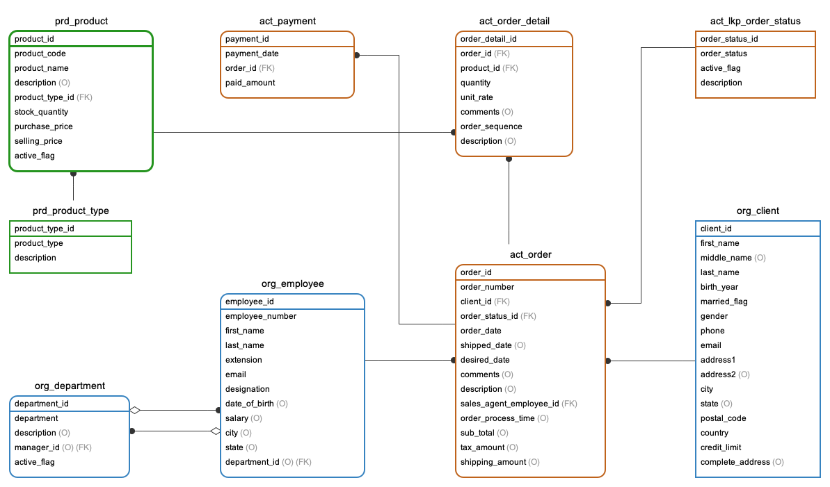
Here, we display entities along with their relationships, attributes, primary keys, foreign keys, and whether attribtues are optional or mandatory. Note that data types are missing from this ERD, this is not specific to any database vendors like MySQL or Oracle.
PHYSICAL DATA MODEL
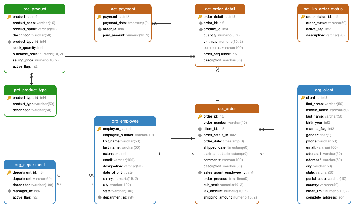
This pertains specifically to certain database vendors such as MySQL, Oracle, PostgreSQL, or MS SQL Server. Therefore, the data types presented here are tailored to a specific database vendor. In this instance, this physical ERD was designed for PostgreSQL, hence you will observe data types intended for PostgreSQL.
Comments Not Found