
MySQL
ERD (Data Model)
An Entity-Relationship Diagram (ERD) is a crucial tool in database design and data modeling. It visually represents the structure of a database by illustrating the entities (such as tables) and the relationships between them. ERDs help in designing a database schema that accurately reflects the data requirements and business rules. They serve as a blueprint for creating and managing databases.
Here’s a breakdown of the key components and steps involved in creating an ERD:
Entities
- Definition: Entities represent objects or concepts that store data. In a relational database, these are typically tables.
- Examples: Employees, Departments, Branches.
-- Example SQL to create an Employees table
CREATE TABLE Employees (
    EmployeeID INT AUTO_INCREMENT PRIMARY KEY,
    EmployeeName VARCHAR(50),
    DepartmentID INT,
    FOREIGN KEY (DepartmentID) REFERENCES Departments(DepartmentID)
);
Attributes
- Definition: Attributes are the properties or characteristics of entities. They represent the columns in a table.
- Examples:
EmployeeName,DepartmentID.
-- Adding attributes to the Employees table
CREATE TABLE Employees (
    EmployeeID INT AUTO_INCREMENT PRIMARY KEY,
    EmployeeName VARCHAR(50),  -- Attribute
    DepartmentID INT,          -- Attribute
    FOREIGN KEY (DepartmentID) REFERENCES Departments(DepartmentID)
);
Relationships
- Definition: Relationships define how entities are related to one another. They are represented by lines connecting entities in an ERD.
- Types: One-to-One, One-to-Many, Many-to-Many.
- Example: An Employee belongs to a Department, so there is a relationship between the Employees and Departments tables.
-- Example SQL to define a relationship
CREATE TABLE Departments (
    DepartmentID INT AUTO_INCREMENT PRIMARY KEY,
    DepartmentName VARCHAR(50)
);

-- Foreign key in Employees table establishes a relationship
ALTER TABLE Employees
ADD FOREIGN KEY (DepartmentID) REFERENCES Departments(DepartmentID);
Cardinality
- Definition: Cardinality indicates the number of instances of one entity that can or must be associated with each instance of another entity.
- Types:
- One-to-One: Each instance of an entity is related to one instance of another entity.
- One-to-Many: Each instance of an entity can be related to multiple instances of another entity.
- Many-to-Many: Multiple instances of one entity are related to multiple instances of another entity.
-- One-to-Many Example: Each Department can have multiple Employees
CREATE TABLE Employees (
    EmployeeID INT AUTO_INCREMENT PRIMARY KEY,
    EmployeeName VARCHAR(50),
    DepartmentID INT,
    FOREIGN KEY (DepartmentID) REFERENCES Departments(DepartmentID)
);
ERD Symbols
- Entities: Rectangles represent entities.
- Attributes: Ovals represent attributes connected to their entity.
- Relationships: Diamonds represent relationships connected to related entities.
- Cardinality: Lines with symbols (such as crow's feet) indicate the nature of the relationship (one, many).
Creating an ERD
- Identify Entities: Determine the main objects or tables required.
- Define Relationships: Establish how these entities interact with each other.
- Draw the Diagram: Use ERD software or drawing tools to create a visual representation.
[Employees] --<belongs to>-- [Departments]- In this simple ERD, the
Employeestable has a relationship with theDepartmentstable, indicating that each employee belongs to a specific department.
By creating and analyzing an ERD, you can ensure that your database design accurately captures the necessary data and relationships, leading to a more efficient and effective database system.
To gain complete access, login with gmail or outlook, no need of signup, click here
Components of an ERD
Entities
These are objects or concepts that can have data stored about them. An entity represents a table in a database. Entities are usually nouns, such as Customer, Order, or Product.
Attributes
These are the data we store about an entity. They represent the columns in a table. For example, an Employee entity might have attributes such as Employee_ID, Name, and Department.
Relationships
These illustrate how entities share information in the database and are the lines that connect entities. Relationships show how two entities share information and interact with each other. They can be one-to-one, one-to-many, or many-to-many.
Primary Key (PK)
This is a unique attribute (or combination of attributes) that identifies a specific instance of an entity. Each entity in the ERD must have a primary key.
Foreign Key (FK)
This is an attribute in one entity that links to the primary key of another entity, establishing a relationship between the two entities.
Types of ERDs
Conceptual ERD
This is the most abstract form of ERD. It focuses on the high-level design and concept without including details like primary keys or attributes. It's used in the initial planning phase.
Logical ERD
This type adds more detail to the conceptual ERD by including key attributes for each entity and relationships. It does not include detailed attributes or methods but focuses on the structure of data.
Physical ERD
This is the most detailed ERD and includes all entities, relationships, key attributes, and constraints. It is directly used to implement the database schema in a specific database management system (DBMS).
CONCEPTUAL DATA MODEL
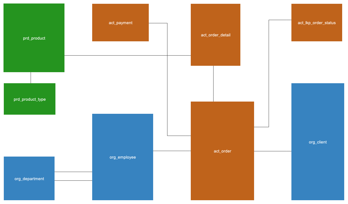
Only entities and their corresponding relationships are depicted here.
LOGICAL DATA MODEL
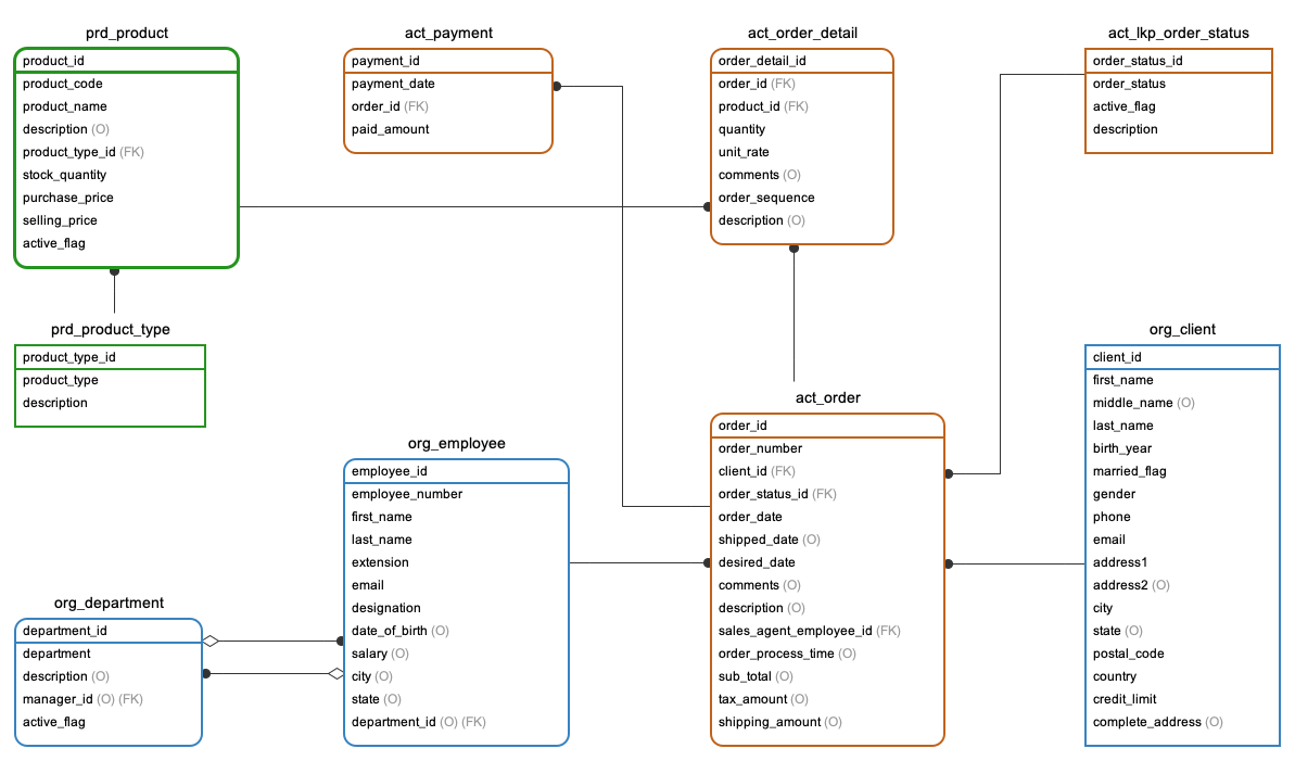
Here, we display entities along with their relationships, attributes, primary keys, foreign keys, and whether attribtues are optional or mandatory. Note that data types are missing from this ERD, this is not specific to any database vendors like MySQL or Oracle.
PHYSICAL DATA MODEL
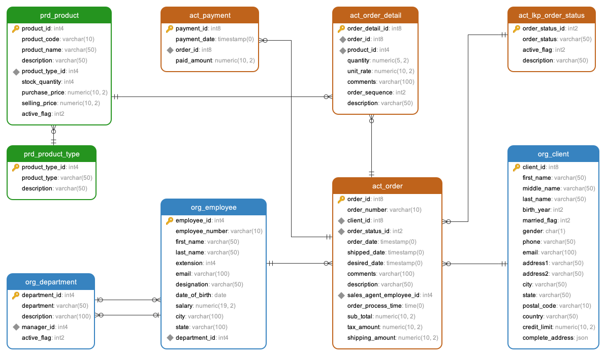
This pertains specifically to certain database vendors such as MySQL, Oracle, PostgreSQL, or MS SQL Server. Therefore, the data types presented here are tailored to a specific database vendor. In this instance, this physical ERD was designed for PostgreSQL, hence you will observe data types intended for PostgreSQL.
Comments Not Found